
One of many aspects that makes the world of software unique is there is a limitless horizon of abstractions possible, "turtles all the way down" so to speak. It's truly an awesome tool, it allows use to move quicker, create expressive APIs for our users, "deploy anywhere™️" and more.
I know when I first made this discovery, I had a palpable sense that I'd be able to create beautiful software, where not a single piece of logic would ever repeat, from the power of my abstractions. But they come at a cost, it might be performance, it might be debuggablity or observability. Or to my horror, maybe the beautiful code I was writing was actually harder to understand, and more brittle than if I hadn't got so high on the abstraction drug.
All this is to say that, like anything, it has pros and cons. Once we've had our come down, we're left with the hard work of figuring out what the right level of abstraction is for any given application. Just as I found myself over-estimating the usefulness of my abstractions, the software industry is starting wind back some abstraction. For example the growing popularity of Typescript speaks to the fact that we're starting to collectively regret dynamic types (somewhat contradictory since typescript is an abstraction of javascript).
Low-code, a case-study in abstraction levels#
Then there is the so called "nocode" movement. In case the name isn't self explanatory enough, in essence it describes tools that allow non-programmers to make applications without code, and it's gaining traction, with conferences and the whole 9-yards.
Personally I don't like these tools, which, to be clear, is not because I think that real programers write
Raw, unadorned, inscrutable hexadecimal numbers.
Directly. *
It's great these tools are available, but ultimately I believe they are the wrong level of abstraction. In fact if one starts using these tools for anything non-trivial, it becomes evident that you're still authoring logic, only without the benefit of version control or tests.
How about low-code as an alternative? Start-up Retool is making a low-code tool aimed at developers. The tool is a mix of drag-n-drop UI elements that can be hooked up to data with SQL queries or customised with your own code. It's a fundamentally different approach where abstractions are not used to shield user's from the under-lying complexities, since the audience are devs and can handle it. They are instead used to remove onerous parts of UI development, but still allowing users to hook back into code for anything custom.
The fact that Retool is marketed for internal tooling is telling, as this unique abstraction level is intended for a specific use-case, again supporting that the level of abstraction should be tailored to the situation.
How does this apply to CodeCAD?#
It goes without saying that I think click-n-drag GUIs are the wrong abstractions for CAD. The potential benefits of:
- 3d diffs
- Proper version control
- Automated tests (unit tests, FEM, or "can this be produced by X machine, mill, 3d-printer etc")
- Build pipelines for artefacts (3d files, BOMs and more)
are too great to ignore, but that doesn't mean we have throw out all UI interactions.
"Sketch-n-extrude" mechanics is the work-horse of traditional CAD packages for a reason, and a UI interface for roughing out these sketches and generating some boilerplate code for the developer to then fill in with variables is a great balance of between UI and code.
Aero-surfaces or stylised-surfaces are cumbersome to create with code, particularly because they often need lots of tweaks, so UI helpers would be of great benefit.
Aside from areas where UI can make up for the weak areas of CodeCAD, there's opportunity for a symbiotic relationship. Leveraging a languages AST, CodeCAD software that understands the relationship between specific sections of code an the corresponding sections of the model and vise-versa. Hovering over the model could highlight relevant code or the opposite. Straddling code and GUI like this allows its users to effortlessly develop a rich mental model of how the software works.
Where has CodeCAD gone wrong? . . . it's CSG#
It's no secret I have concerns about CSG and working primarily with 3d-primitives. It has its place but it's been over-emphasised.
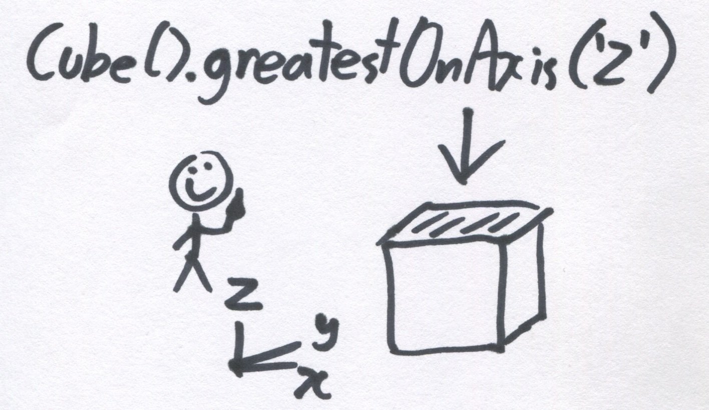
Being able to get a 3d shape from a single line like cube() might feel productive, but it's too much of an abstraction.
How do you deal with the cube once it's created? Lets say you want to select one of the faces to do more work, is there system of for selecting faces by what axis they're aligned with?
Is it deterministic? What would happen if we rotate before we select?
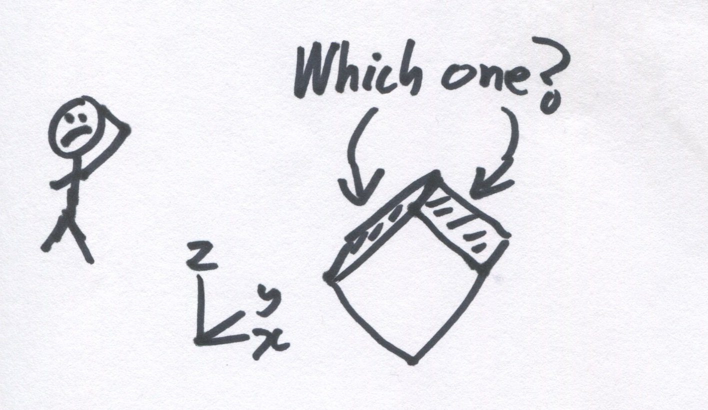
Or do we simply order the faces so you can learn the convention and then select one of the 6?
cube().getFace(5)Both of these feel cumbersome. A "sketch" is a much better place to start from; it's a better primitive. Let use the cube again by extruding a 2d sketch. The following examples use an object-oriented style syntax, but it's all hypothetical so don't take it too seriously.
square = sketch([0,0]) .verticalLineTo(10) .horizontalLineTo(10) .verticalLineTo(0) .close()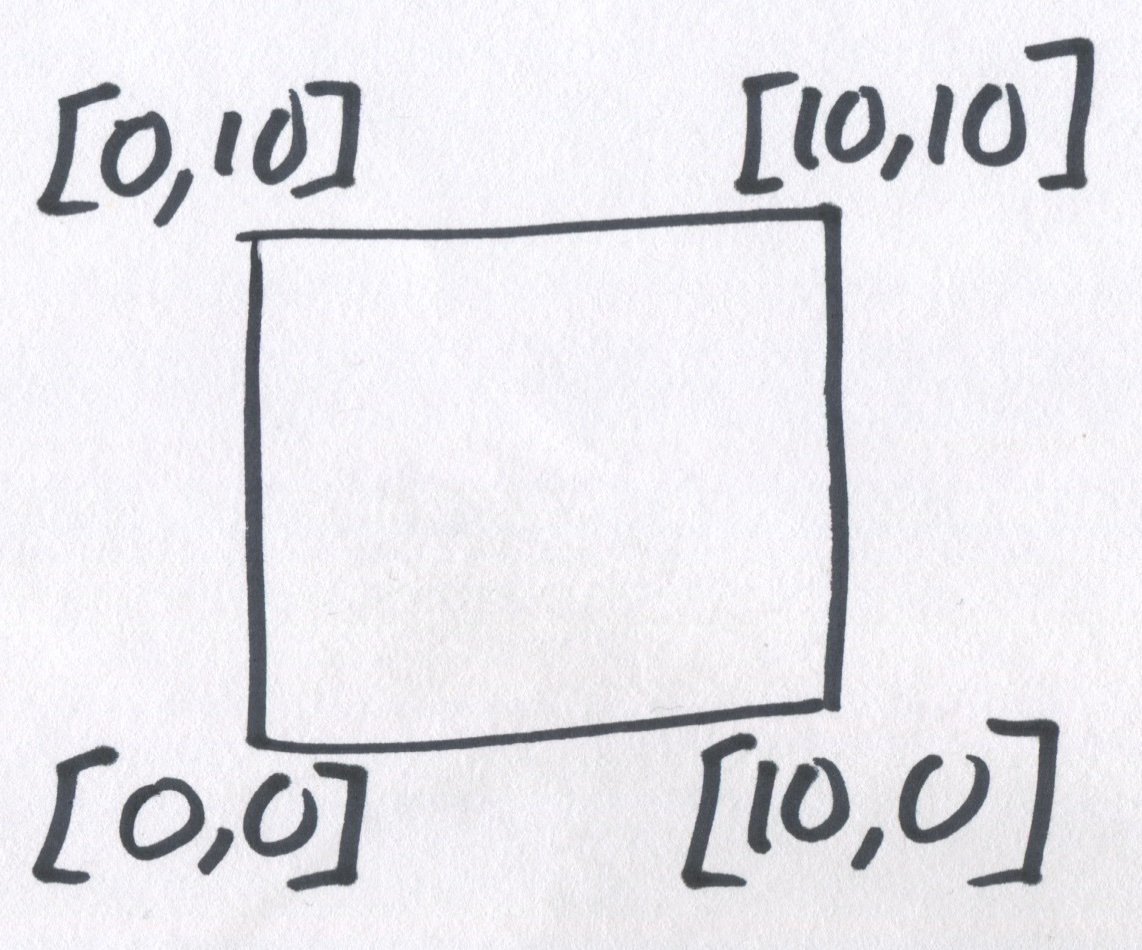
square = sketch([0,0])  .verticalLineTo(10)  .horizontalLineTo(10)  .verticalLineTo(0)  .close()
extrude(square, 10)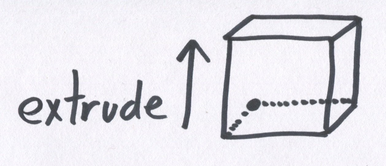
Because we've constructed each edge of a square before extruding we can label/tag those edges, giving us an intuitive way of selecting both edges from the sketch and the face that edge forms.
square = sketch([0,0])  .verticalLineTo(10).tag('myEdge')  .horizontalLineTo(10)  .verticalLineTo(0)  .close()
cube = extrude(square, 10)
cube.baseEdge('myEdge')cube.face('myEdge')cube.headEdge('myEdge')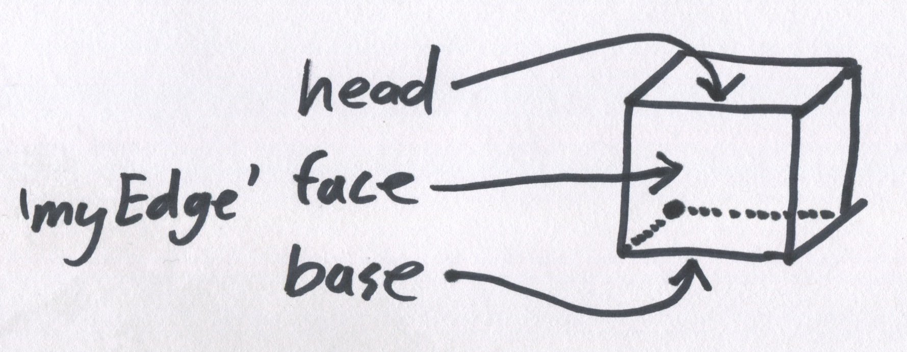
We are now able to take surgical actions on any edge or face we like. We could start a new sketch on one of the existing faces, or fillet one of the edges.
cube.headEdge('myEdge').fillet(3)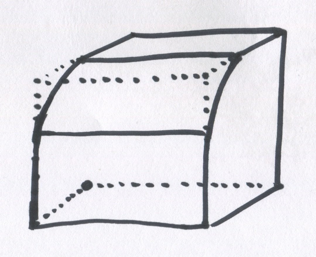
Filleting edges are interesting because edges don't always come directly from sketches, but instead from combining shapes. Imagine two intersecting extrusions (labels A & B show the extrusion direction, and there are two arbitrary faces labeled we want to fillet between).
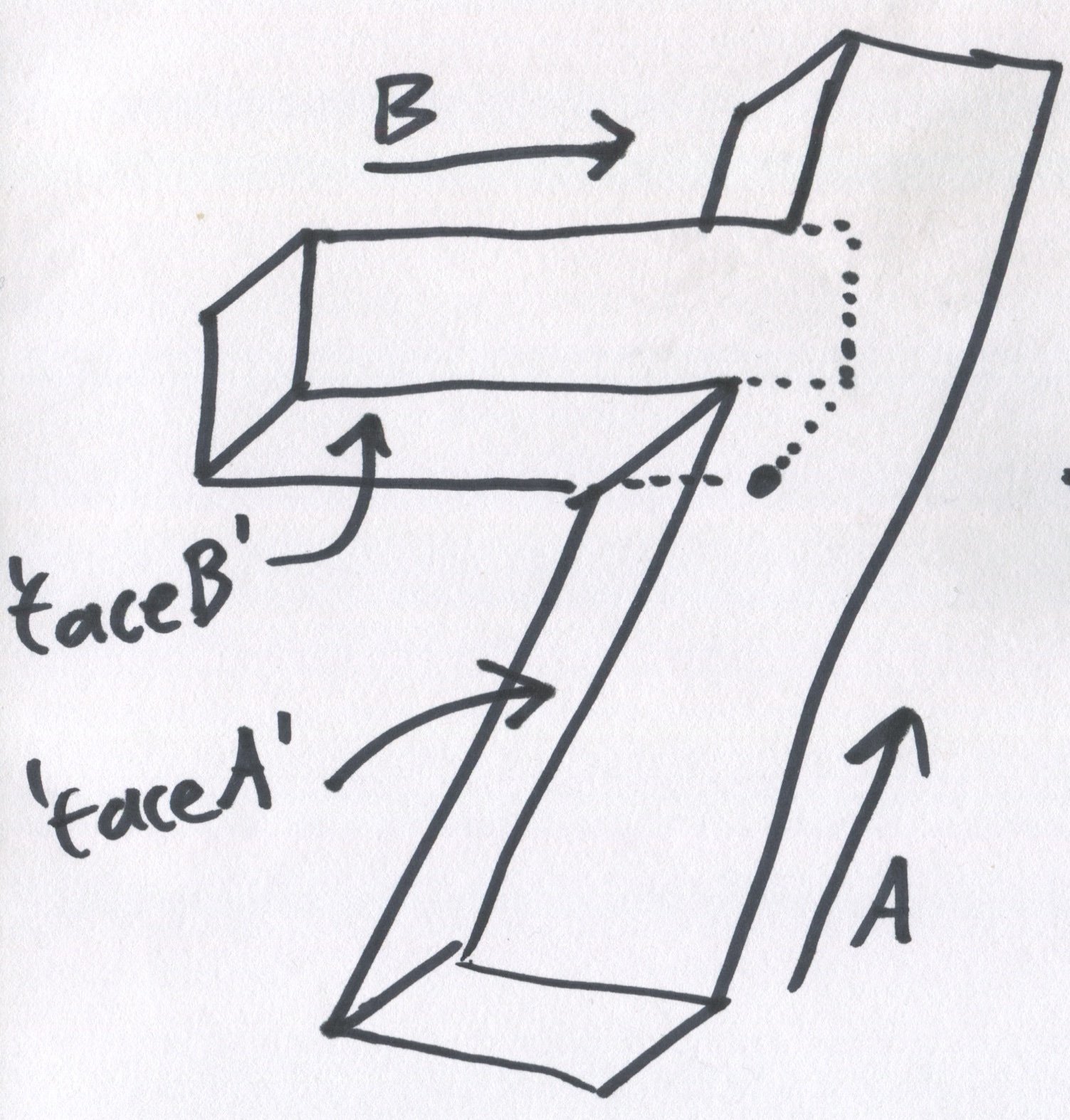
If we needed to add a fillet to where the two shapes meet, we could develop a syntax for defining a minimum radius when two shapes are merged.
minRadius = 2union(minRadius, [ extrusionA, extrusionB,])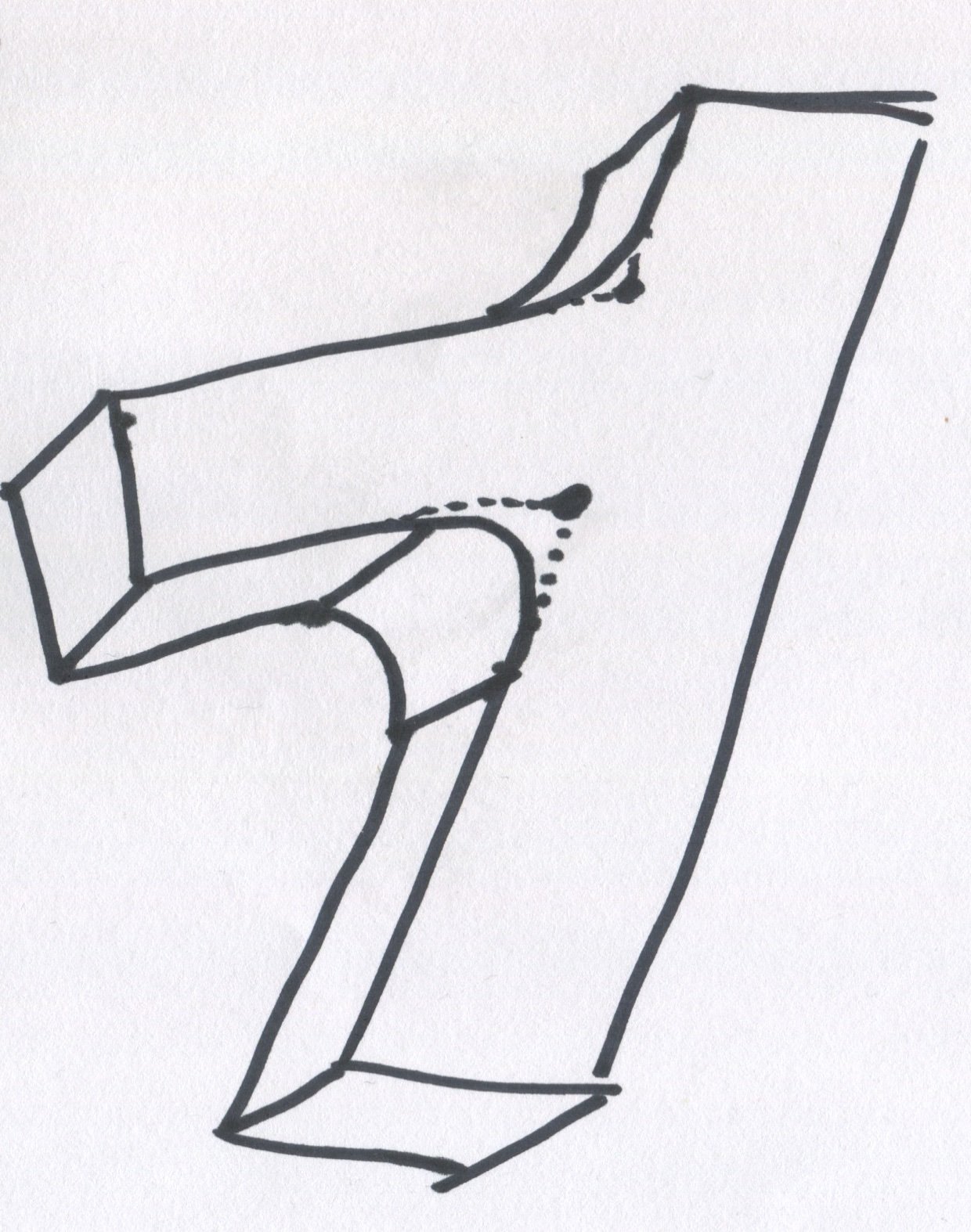
However, this is rather crude, and it's important we're able to be specific about what edges are filleted (the above shows two edges that got filleted together). Because any given edge is formed where two faces intersect, if we have previously tagged those faces we can use that to select and surgically fillet the edge.
edgeFromFaces( extrusionA.face('nameA') extrusionB.face('nameA')).fillet(2)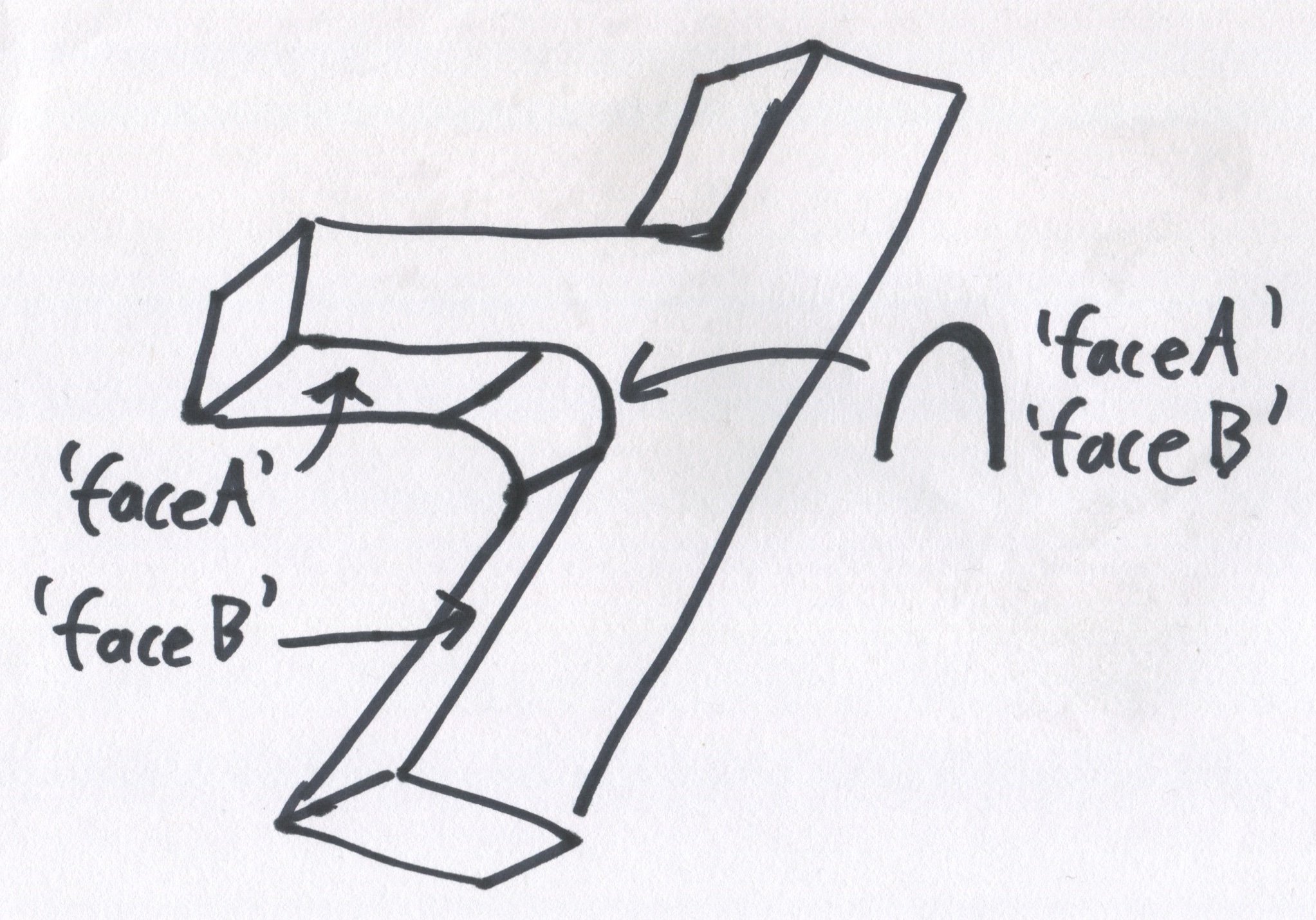
This approach would be robust against minor changes in the rest of the program. In the situation the extrusions no longer overlap and hence the faces don't intersect to form an edge, a descriptive error can be thrown.
Line XYZ: Unable to find edge:
    edgeFromFaces(....^      extrusionA.face('nameA')      extrusionB.face('nameB')    ).fillet(2)
Faces with tags 'nameA' and 'nameB' do not intersect.So far we've talked about the sketch, edge and face concepts. The reason these are so useful is that they're conceptually linked to a boundary-representation, pairing well with a B-Rep kernel. Extending these, surface and vertice would also be useful. Once we've used two faces to fillet an edge, we could use a face to determine the length of an extrusion.
Let's say we had a existing shape and a new sketch that we wanted to extrude through to the last column.
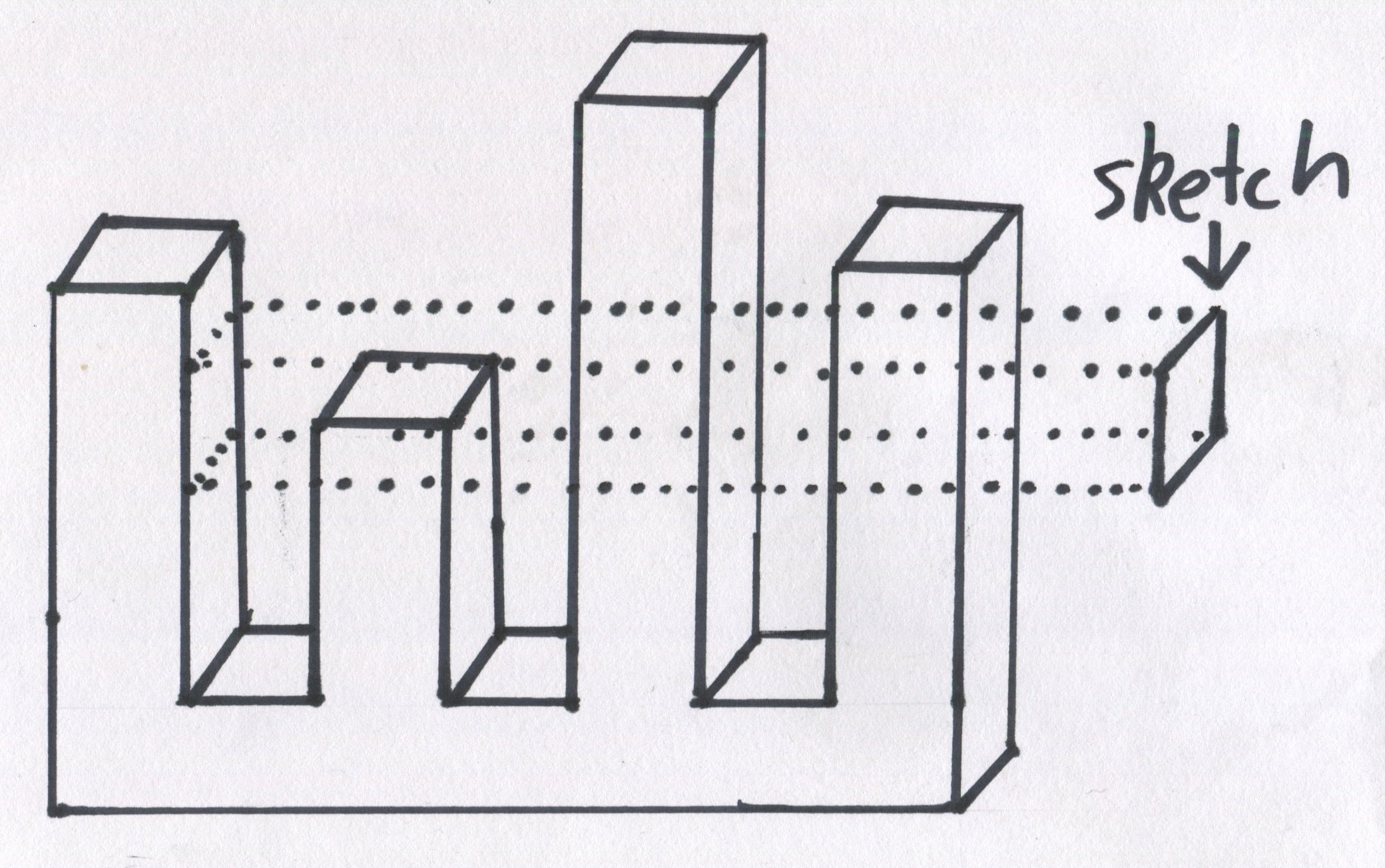
If we had previously tagged that last face, instead of calculating how long to make the extrusion we can instead extrude to that face.
sketch.extrudeToFace( otherShape.face('myFace'))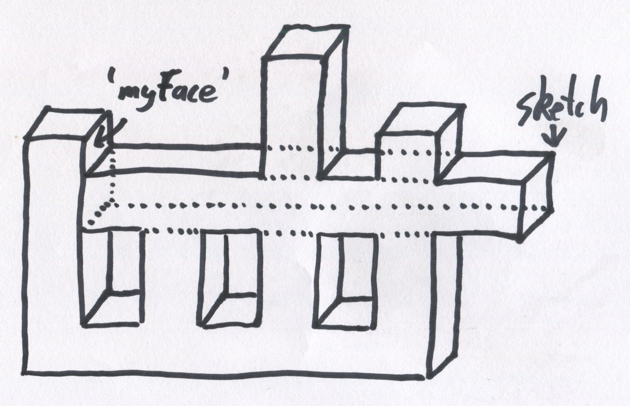
Similarly, extrudeToSurface, extrudeToVertice etc. would work.
Applied to CSG#
In cases where CSG is a good idea, we can still carry our tagged faces, edges etc. through the operation. Let's say we want to subtract the rectangular prism on the right away from the cylinder.
subtract( myCylinder, myRectangularPrism)Any tagged faces will transfer over, i.e 'myFace' in this example.
The nitty gritty of sketches#
The previous square sketch example I gave is simplistic to say the least. Once you mix in radii, splines, tangents and all manner of constraints, it quickly becomes complex, and a good API to capture all the subtleties is challenging. I see two main approaches to this problem.
Option a) direct conversion for GUI CAD#
The workflow GUI-CAD is generally
- Draw a sketch that's roughly in the right shape, it will include all the arcs and edges it needs but dimensions won't be correct.
- Add constraints, such as forcing two lines to be parallel, defining the length of a section or the radius of an arc etc.
Trying to capture this workflow directly in an API is, in my opinion, challenging, and my attempts so far have resulted in hard to read code. For example one approach would be to give each point in a closed sketch a name and then add an array of constraints that apply to those names.
Given a simple shape made of two lines connected by tangential arcs
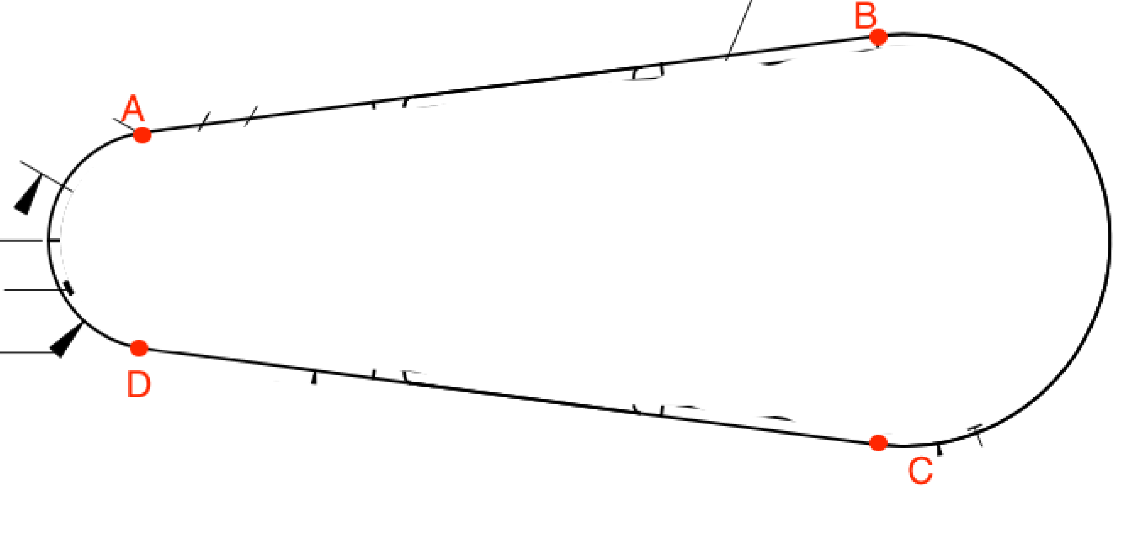
The resulting code is hard to read and decipher (especially for a simple case).
{ points: ['A', 'B', 'C', 'D'], constraints: { tangent: ['A', 'B', 'C', 'D'], line: [['A', 'B'], ['C', 'D']], arc: [ { points: ['B', 'C'], radius: 1, centerPointName: 'centerBC' }, { points: ['D', 'A'], radius: 1.89, centerPointName: 'centerDA' } ], vertical: [['B', 'C'], ['D', 'A']] horizontal: [['centerBC', 'centerDA']] coordinates: [{ point: 'centerDA', coords: [0, 0], }] horizontalDistance:[{ points: ['centerBC', 'centerDA'], // assuming the radiuses were in variables this would become something like: // partLength - keyOuterRadius - radius2 distance: 9.75 - (1.89 + 1) }] }}It's possible that I'm just going about it wrong, and there is a much more intuitive API I haven't thought of.
Option b) polygon inspired sketch system#
The closest thing to "sketch" in most Code-CAD is the polygon, i.e. listing out a number of points. This is both easy and hard to read:
- Easy because following from one point to the next is an easy way to keep track of what's going on.
- Hard because it's not intuitive to read points, plus there is inherently a lot of "duplication" for horizontal and vertical lines. For example the points for a square might be:
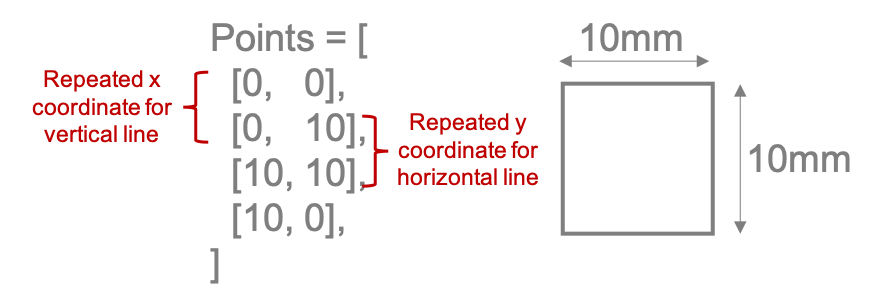
Plotting points with a polygon can often be difficult as it requires calculating complex interactions of geometry i.e. getting a point to land on the tangent of an arc or where two lines would intersect. These aren't difficult to calculate in any one situation, but a part could contain hundreds of these kinds of calculations, so helpers of some kind are needed.
An approach I've tried by extending the cascadeStudio API keeps the "series of points forming a close shape" of the polygon with a series of helpers. Here's a sample:
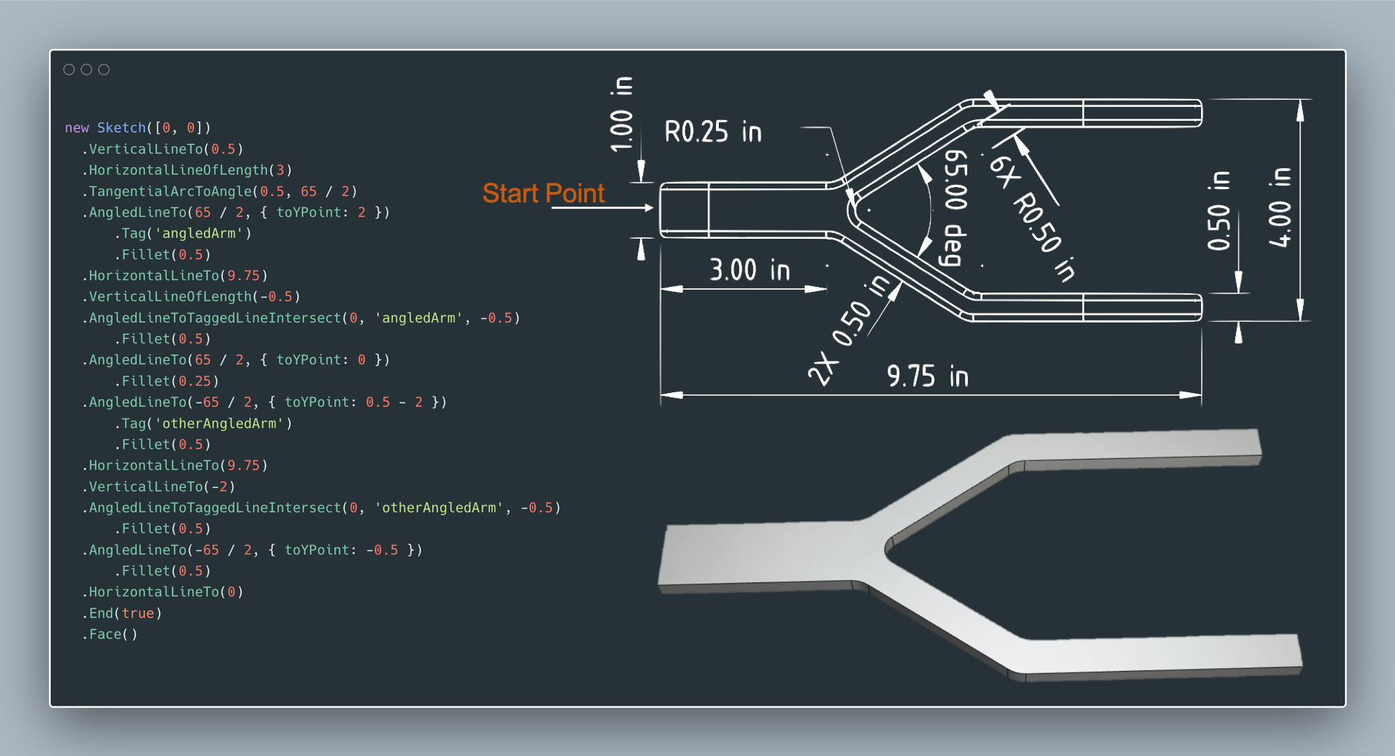
One major challenge with this approach is how to make it play nice with a GUI process, as it relies more on the author to take implicit care of constraints instead of explicitly stating them. "Constraining" two lines to be parallel with this approach doesn't make much sense since the author would have defined both lines as having the same angle, in fact both lines could simply use the same variable that defines the angle.
There's still hard work to be done#
You're now privy to a bunch of ideas that have been kicking around and developing in my head for some time. Some of them are good while others need more development, like the discussion of sketches at the end. But that's the rub, CodeCAD is a great level of abstraction for CAD, but it's going to take some work to see it fully form.
Other resources#
- I was recently inspired by Jessie Frazelle's blog post on the topic to put much of my own ideas out there
- To see more of my sketch-API attempt with more code examples the CascadeStudio PR is worth reading through
- Here's a maintained list of opensource CodeCAD tools
- CadQuery has escaped the CSG mindset and deserves credit for that
- The urge for a good sketch API has been with me for some time, first starting with my Round-Anything library