Adding Clearances
Since we've started thinking about how the hinge will be assembled with the pin taper, we also need to think about tolerances and clearance gaps. Because we want this hinge to be "print in place" which mean it prints pre-assembled, we need to add clearance gaps so that our part doesn't print solid!
Let start by adding a clearance variable and first thing we need to do is extrude our hingeBodyHalf slightly less than hingeLength/2 since there needs to be some play between the two halves.
clearance=0.2;module hingeBodyHalf() { linear_extrude(hingeLength/2-clearance/2){ // ... rest of module definition}Oh no! there's now a gap between our pin and hingeBodyHalf
Here's the fix for that:
hingeHalfExtrudeLength=hingeLength/2-clearance/2;
module hingeBodyHalf() {  linear_extrude(hingeHalfExtrudeLength){  // ... rest of module definiton}
module pin() { translate([0,pivotRadius,hingeHalfExtrudeLength]){ cylinder(h=hingeLength/2+clearance/2, r1=pinRadius, r2=pinRadius+pinTaper); }}We've done something new here, we've defined a variable with other variables and some arithmetic with hingeHalfExtrudeLength=hingeLength/2-clearance/2;.
This variable is then used both in hingeBodyHalf and pin.
The benefit of doing so is if we need to update this length again we only need to update it in one place since both of the modules need the same calculated length.
Also notice that've we increased the length of the cylinder too so that it reaches the full hingeLength.
Much better
We still have more work to do on the pin though.
We want to re-use the pin to "subtract" its shape from the other half of the hinge, basically we can use our current pint to make a hole.
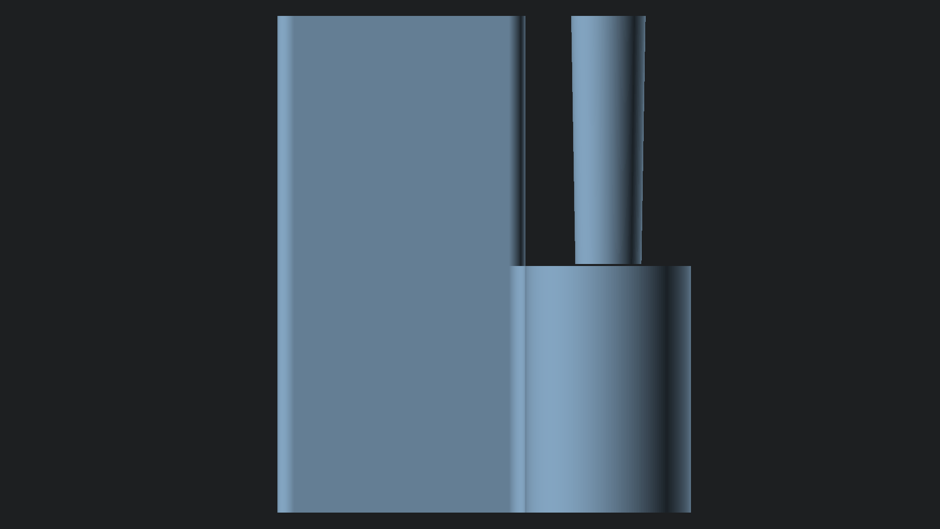
Lets make a temporary new module called pin2. In this new module and we're going to introduce a new function rotate to re-orientate the pin
module pin2() {  translate([0,pivotRadius,hingeHalfExtrudeLength]){    rotate([0,45,0]){      cylinder(h=hingeLength/2+clearance/2, r1=pinRadius, r2=pinRadius+pinTaper);    }  }}
hingeBodyHalf();pin2();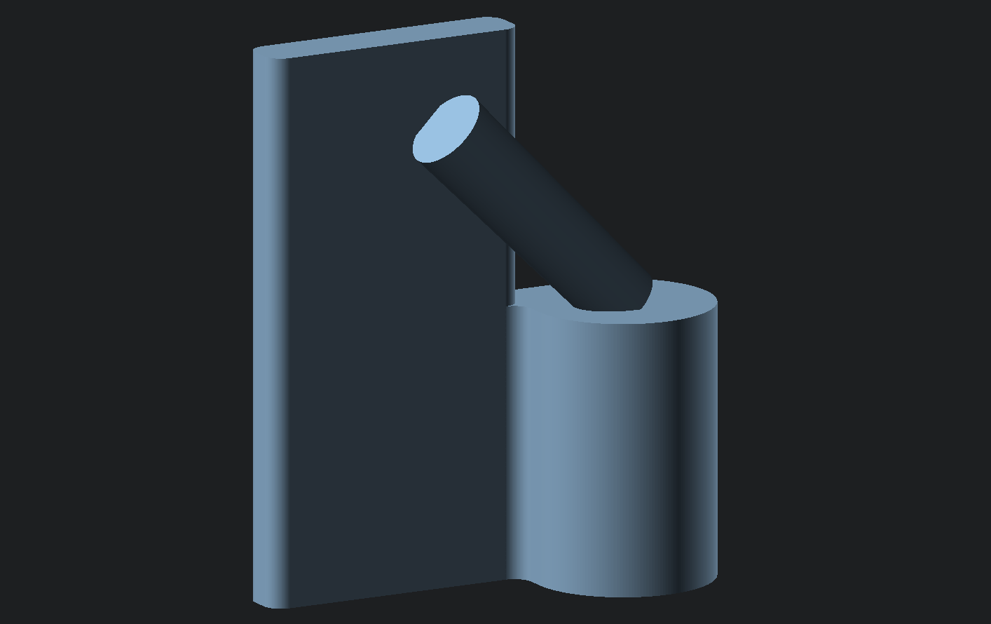
This is not where we want to leave our pin, but it's a good way to introduce rotate as well as using multiple modifiers, i.e. we're using both translate and rotate together here.
rotate is similar to translate in that it takes an argument [x, y, z] but instead of moving, it rotates about each of those axes. In the above example of [0, 45, 0] it's as if were were to put a pin into the object along the y axis and then rotate 45 degrees around that pin.
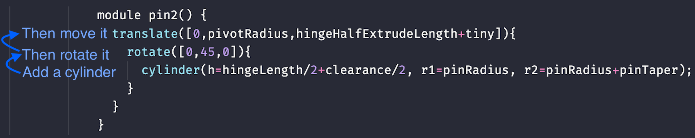
How To Read Chained Operations#
Notice the order that we applied the rotate and transform we applied the rotate first and then thetransform.
This might seem counter intuitive because translate is on top, but nesting operations should be read from the most nest outward in openscad.
Here's the correct way to read the above code:
The same thing applies to hingeBodyHalf that should read as follows:
// read as// 1) Add circle, square and hingeBaseProfile// 2) Apply an offset of 1 (far right offset)// 3) then on offset of -2 (middle) then an offset of 1 (far left)// 4) Extrude the 2d shape of hingeHalfExtrudeLengthmodule hingeBodyHalf() { linear_extrude(hingeHalfExtrudeLength){ offset(1)offset(-2)offset(1){ translate([0,pivotRadius,0]){ circle(pivotRadius); } square([pivotRadius,pivotRadius]); hingeBaseProfile(); } } linear_extrude(hingeLength){ offset(1)offset(-1)hingeBaseProfile(); }}Back to our pin and rotate. The reason we rotate first is because openscad shapes always rotates around the origin point [0,0,0] and translating first can make things very confusing, in general you should ALWAYS rotate first unless you have a good reason not to.