API reference and examples
A detailed look at all the Round-Anything library functions and modules. For a general overview of features, how to get started and the motivation behind the library, see the written overview or the video overview.
polyRound#
Function for adding radii to any point of a polygon.
polyRound function returns an array of 2d-points, therefore it's typical to paired it with polygon and linear_extrude.
use: polygonArray = polyRound(radiipoints,fn,mode);
Arguments are:
radiiPoints: nest array of[x, y, r]points. That is x-y coordinates and the radius for that point, .ie.[[x1, y1, r1],[x2, y2, r2] ...]fn: The amount of point each radius is subdivided.mode: Three different modes for handling conflicting radii:- Default, automatically reduces radii to stop conflicts.
- Debugging mode, print reduced radii to the console.
- Radii conflict resolution disabled.
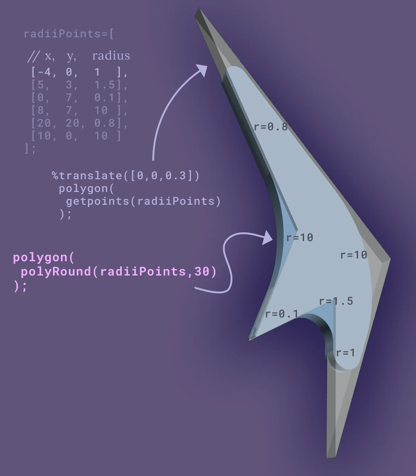
radiiPoints=[[-4,0,1],[5,3,1.5],[0,7,0.1],[8,7,10],[20,20,0.8],[10,0,10]];polygon( polyRound(radiiPoints,30));By default polyRound will reduce radii to stop any two subsequent radii from conflicting.
To further understand how the radii conflict resolution works here's an example of that.

// example of radii conflict handling and debuging featurefunction makeRadiiPoints(r1, r2)=[[0,0,0],[0,20,r1],[20,20,r1],[20,0,0]];
// the squre shape being 20 wide, two radii of 10 both fit into the shape (just)translate([-25,0,0])polygon(polyRound(makeRadiiPoints(10,10),50));
// radii are too large and are reduced to fit and will be reduce to 10 and 10translate([0,0,0])polygon(polyRound(makeRadiiPoints(30,30),50));
// radii are too large again and are reduced to fit, but keep their ratios.// r1 will go from 10 to 4 and r2 will go from 40 to 16translate([25,0,0])polygon(polyRound(makeRadiiPoints(10,40),50));
// mode 2 = no radii limitingtranslate([50,0,0])polygon(polyRound(makeRadiiPoints(15,20),50,mode=2));Also see the radii conflict deep-dive if you want to know more.
polyRoundExtrude#
It's the 3d/Module version of polyRound. Creating a extusion of a polyRound shape with fillets on the end.
Use: polyRoundExtrude(radiiPoints,length,r1,r2,fn,convexity)
radiiPoints: list of[x, y, r]points.length: length of the extrusion.r1,r2: Start and end radii.fn: amount of subdivisions for forming the polyhedron.convexity: convexity of the underlying polyhedron.
This module is similar to extrudeWithRadius in purpose, though by using radiiPoints directly instead of a generic 2d child it's able to offer smoother curves in a more preformant manner.
It is recommended over extrudeWithRadius where possible.
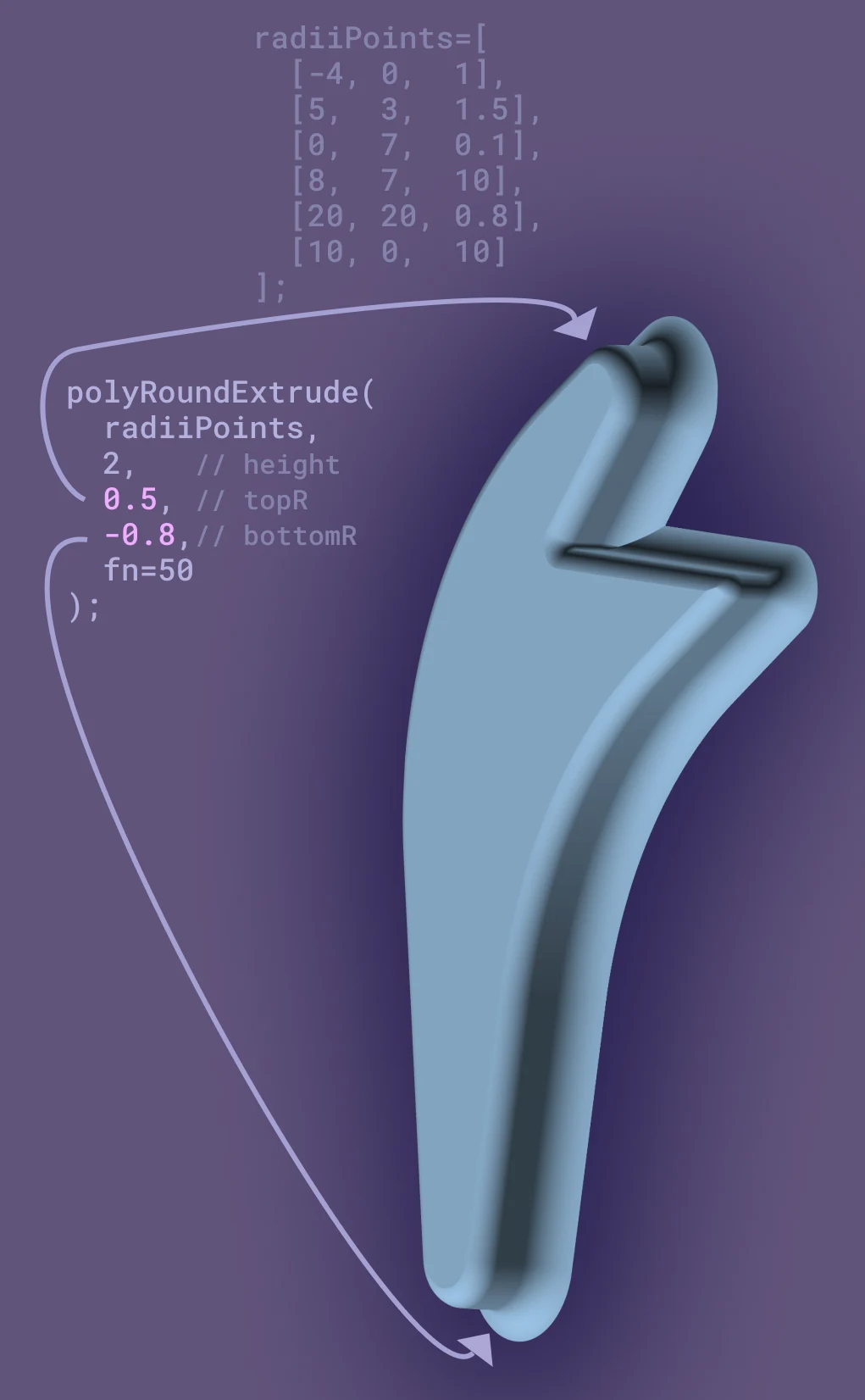
radiiPoints=[[10,0,10],[20,20,1.1],[8,7,10],[0,7,0.3],[5,3,0.1],[-4,0,1]];polyRoundExtrude(radiiPoints,2,0.5,-0.8,fn=50);Negative fillets on the end of extrusions can be useful when:
- An extrusion needs to mate with flat surface
- Creating holes with transitioning fillets.
translateRadiiPoints#
Function for moving radii points, to aid in their reuse.
use: translatedRadiiPoints = translateRadiiPoints(radiiPoints, tran, rot);
radiiPoints: list of[x, y, r]points to be translated.tran:[x, y]translation points.rot: how to rotate the points on the z-axis.
Because the function returns radiiPoints, they need to be used with polyRound before used as a polygon.
translateRadiiPoints is typically employed to re-use points multiple times in one part.
In order to make this work, several series of points are combined concat.
nutW=5.5;   nutH=3; boltR=1.6;minT=2;     minR=0.8;function nutCapture(startAndEndRadius=0)=[  [-boltR,        0,         startAndEndRadius],  [-boltR,        minT,      0],  [-nutW/2,       minT,      minR],  [-nutW/2,       minT+nutH, minR],  [nutW/2,        minT+nutH, minR],  [nutW/2,        minT,      minR],  [boltR,         minT,      0],  [boltR,         0,         startAndEndRadius],];translate([-5,0,0])polygon(polyRound(nutCapture(),20));
negativeNutCapture=translateRadiiPoints(nutCapture(),tran=[5,0]);rotatedNegativeNutCapture=translateRadiiPoints(nutCapture(1),tran=[20,5],rot=90);aSquare=concat( [[0,0,0]], negativeNutCapture, [[20,0,0]], rotatedNegativeNutCapture, [[20,10,0]], [[0,10,0]]);polygon(polyRound(aSquare,20));shell2d#
Module that will create a shell out of any 2d object. subsequent children fill the shell.
Use:
shell2d(offset1,offset2=0,minOR=0,minIR=0){ // shell child // fill children}where:
offset1,offset2: Two offsets that together define the thickness of the shell and are measured relative to the perimeter of the original 2d shape. Negative value go towards the centre of the shape, positive value go away.minOR,minIR: minimum radii can be defined, if you're using this in conjunction with ployRound they can be ignored for the most part.
Here's a simple example.
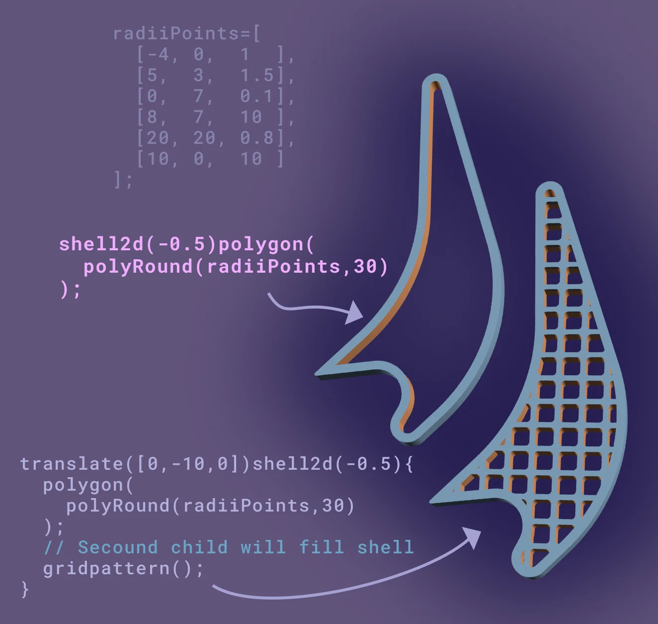
radiiPoints=[[-4,0,1],[5,3,1.5],[0,7,0.1],[8,7,10],[20,20,0.8],[10,0,10]];shell2d(-0.5)polygon(polyRound(radiiPoints,30));translate([0,-10,0])shell2d(-0.5){ polygon(polyRound(radiiPoints,30)); translate([8,8])gridpattern(memberW = 0.3, sqW = 1, iter = 17, r = 0.2);}
beamChain#
This function takes a series of radii points and creates a beam of constant thickness with each pair of points.
Use: newRadiiPoints = beamChain(radiiPoints,offset1=0.02, offset2=-0.02
radiiPoints: radiiPoints: list of[x, y, r]points. Note, negative radiuses only allowed for the first and last radii points.offset1,offset2: The two offsets that give the beam it's thickness. When using withmode=2onlyoffset1is needed as there is no return path for the polygon.minR: Min radius, if all of your radii are set properly within the radii points this value can be ignoredstartAngle,endAngle: Angle at each end of the beam, different mode determine if this angle is relative to the ending legs of the beam or absolute.mode: Different modes for how the end angles are handled and if the return path of the beam polygon in included.
startAngle and endAngle are relative to the angle of the last two points and equal 90deg if not defined.
Only the forward path is defined, useful for combining the beam with other radii points, see examples for a use-case.
startAngle and endAngle are absolute from the x axis and are 0 if not defined.
This function is very flexible in how it's used so below are a series of examples increasing complexity.
Because it returns a new list of radiiPoints, it can safetly used with polyRoundExtrude.
The following shows how a series of points can form the bean chain, how radii are added and defining the thickness of the beams
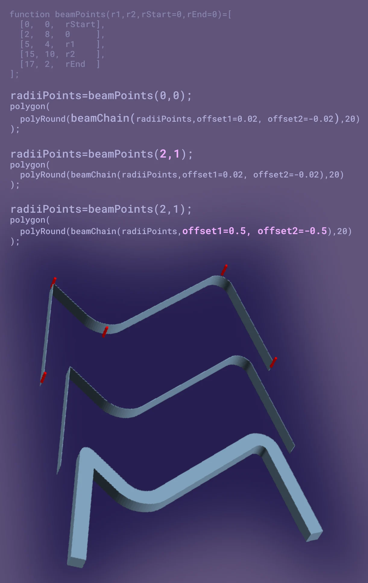
function beamPoints(r1,r2,rStart=0,rEnd=0)=[[0,0,rStart],[2,8,0],[5,4,r1],[15,10,r2],[17,2,rEnd]];
// chained lines by themselvestranslate(){  radiiPoints=beamPoints(0,0);  for(i=[0: len(radiiPoints)]){color("red")translate([radiiPoints[i].x,radiiPoints[i].y,0])cylinder(d=0.2, h=1);}  polygon(polyRound(beamChain(radiiPoints,offset1=0.02, offset2=-0.02),20));}

// Add some radii to the line transitionstranslate([0,-7,0]){  radiiPoints=beamPoints(2,1);  for(i=[0: len(beamPoints(2,1))]){color("red")translate([radiiPoints[i].x,radiiPoints[i].y,0])cylinder(d=0.2, h=1);}  polygon(polyRound(beamChain(radiiPoints,offset1=0.02, offset2=-0.02),20));}
// Give make the lines beams with some thicknesstranslate([0,-7*2,0]){ radiiPoints=beamPoints(2,1); polygon(polyRound(beamChain(radiiPoints,offset1=0.5, offset2=-0.5),20));}The next example shows adding a angle and filleting radius to the end of the beams
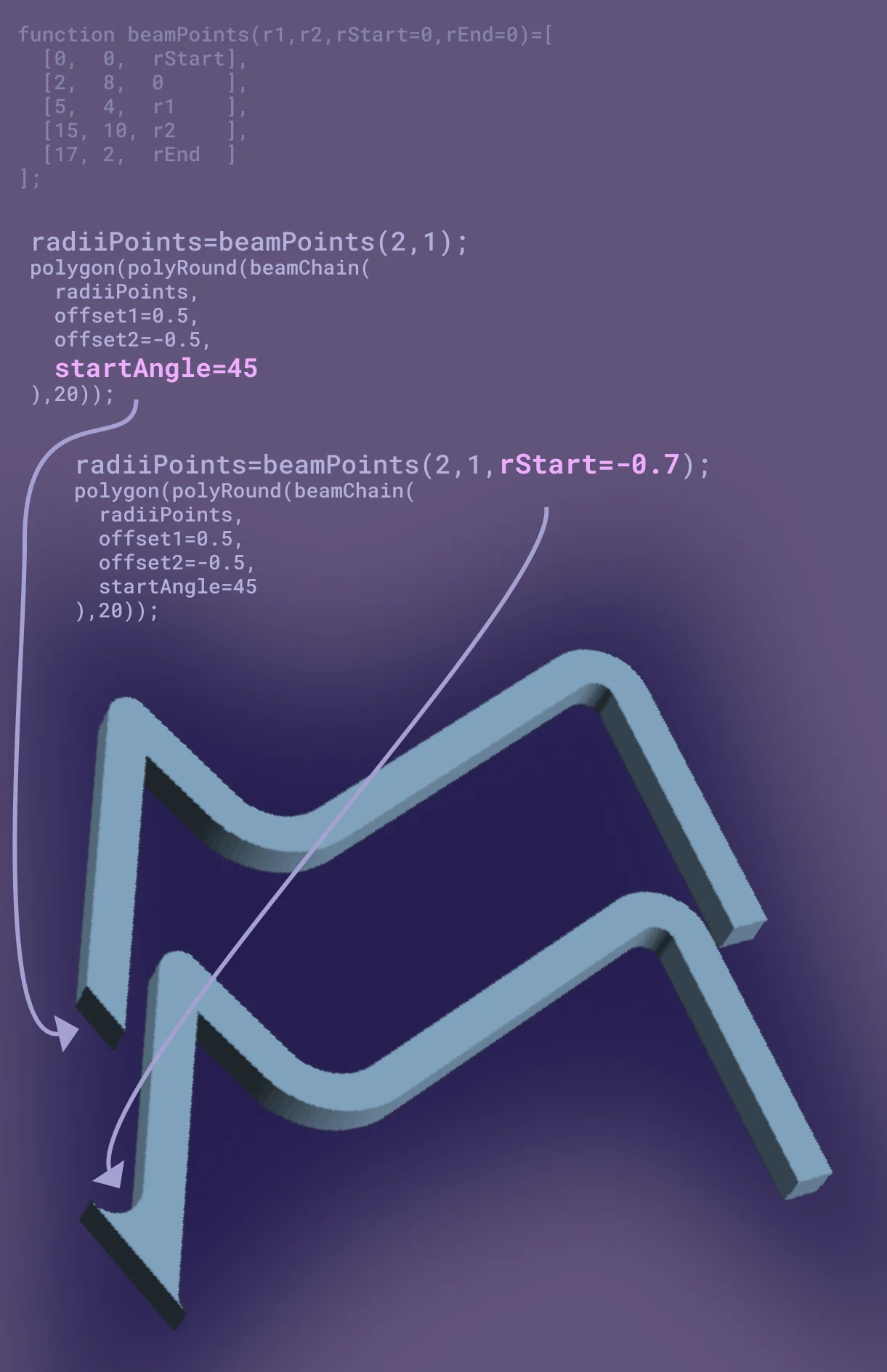
function beamPoints(r1,r2,rStart=0,rEnd=0)=[[0,0,rStart],[2,8,0],[5,4,r1],[15,10,r2],[17,2,rEnd]];
// Add an angle to the start of the beamtranslate([0,-7*3,0]){  radiiPoints=beamPoints(2,1);  polygon(polyRound(beamChain(radiiPoints,offset1=0.5, offset2=-0.5, startAngle=45),20));}
// Put a negative radius at the start for transationing to a flat surfacetranslate([0,-7*4,0]){ radiiPoints=beamPoints(2,1,rStart=-0.7); polygon(polyRound(beamChain(radiiPoints,offset1=0.5, offset2=-0.5, startAngle=45),20));}Lastly the following shows how seperating the beams polygong path into forward and return paths allows extra polgon points at the ends of the beam. The advantage of this over regular union is adding a transitioning radius between the beam and the extra points.
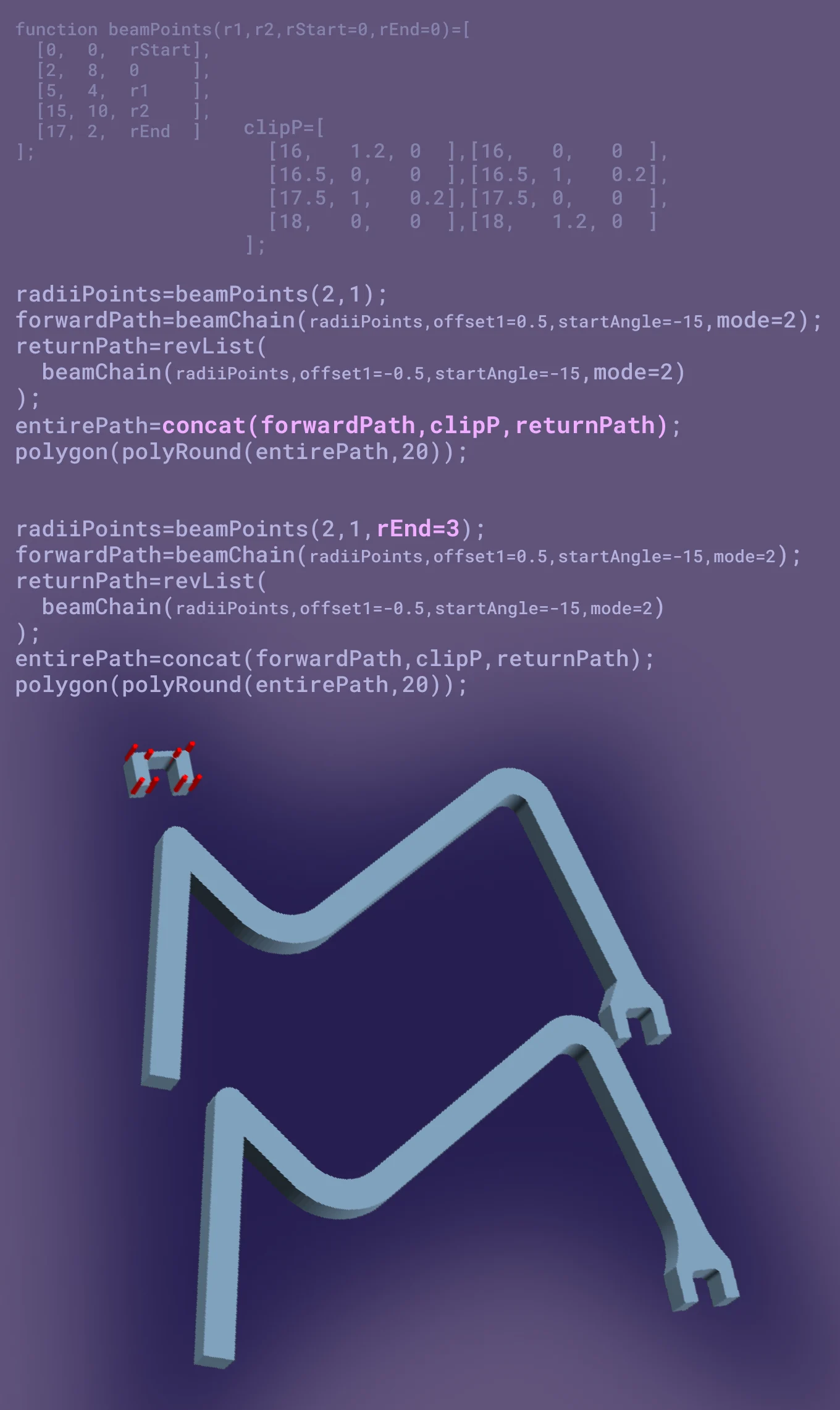
function beamPoints(r1,r2,rStart=0,rEnd=0)=[[0,0,rStart],[2,8,0],[5,4,r1],[15,10,r2],[17,2,rEnd]];
// Define more points for a polygon to be atteched to the end of the beam chainclipP=[[16,1.2,0],[16,0,0],[16.5,0,0],[16.5,1,0.2],[17.5,1,0.2],[17.5,0,0],[18,0,0],[18,1.2,0]];translate([-15,-7*5+3,0]){ for(i=[0:len(clipP)-1]){color("red")translate([clipP[i].x,clipP[i].y,0])cylinder(d=0.2, h=1);} polygon(polyRound(clipP,20));}
// Attached to the end of the beam chain by dividing the beam paths in forward and return and// concat other polygon inbetweentranslate([0,-7*6,0]){ radiiPoints=beamPoints(2,1); forwardPath=beamChain(radiiPoints,offset1=0.5,startAngle=-15,mode=2); returnPath=revList(beamChain(radiiPoints,offset1=-0.5,startAngle=-15,mode=2)); entirePath=concat(forwardPath,clipP,returnPath); polygon(polyRound(entirePath,20));}
// Add transitioning radii into the end polygongtranslate([0,-7*7-2,0]){ radiiPoints=beamPoints(2,1,rEnd=3); forwardPath=beamChain(radiiPoints,offset1=0.5,startAngle=-15,mode=2); returnPath=revList(beamChain(radiiPoints,offset1=-0.5,startAngle=-15,mode=2)); entirePath=concat(forwardPath,clipP,returnPath); polygon(polyRound(entirePath,20));}
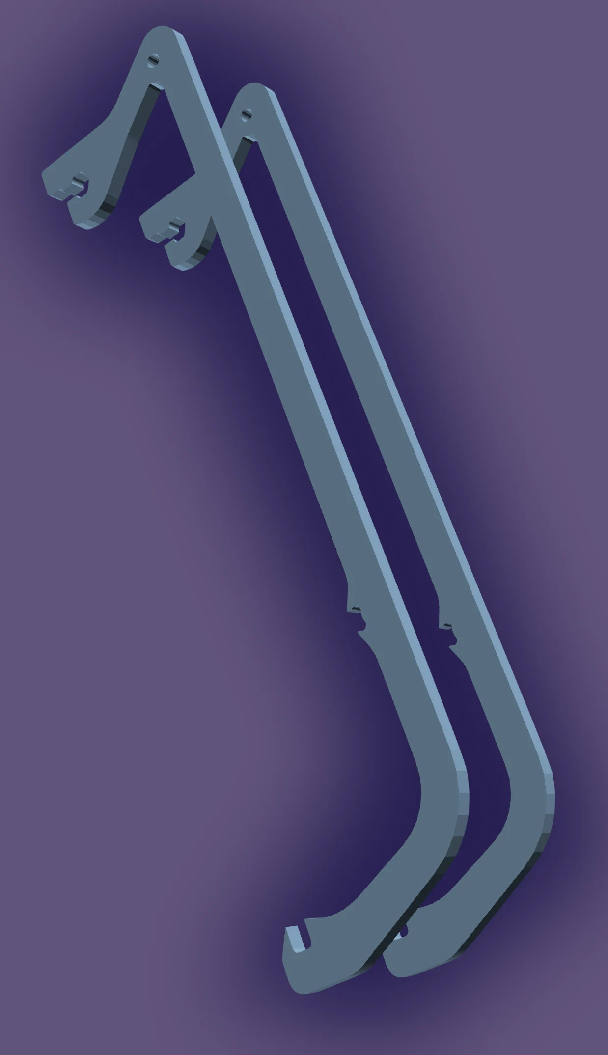
// Define multiple shells from the the one set of pointstranslate([0,-7*9,0]){ for(i=[0:2]){polygon(polyRound(beamChain(beamPoints(2,1),offset1=-1+i*0.4, offset2=-1+i*0.4+0.25),20));}}
mirrorPoints#
Function for mirroring radiiPoints. The advantage of this over other mirror techniques is when using radii points it allows for adding a radius to the transition of the two halves.
use: mirroredRadiiPoints = mirrorPoints(radiiPoints, rot, endAttenuation)
radiiPoints: radiiPoints: list of[x, y, r]points.rot: angle of rotation.endAttenuation: [start, end]. Amount of points to be removed from the start and end of the radiiPoints. Its purpose is to remove single points from the ends if they lie right on the mirror axis and would cause two points on top of each other.
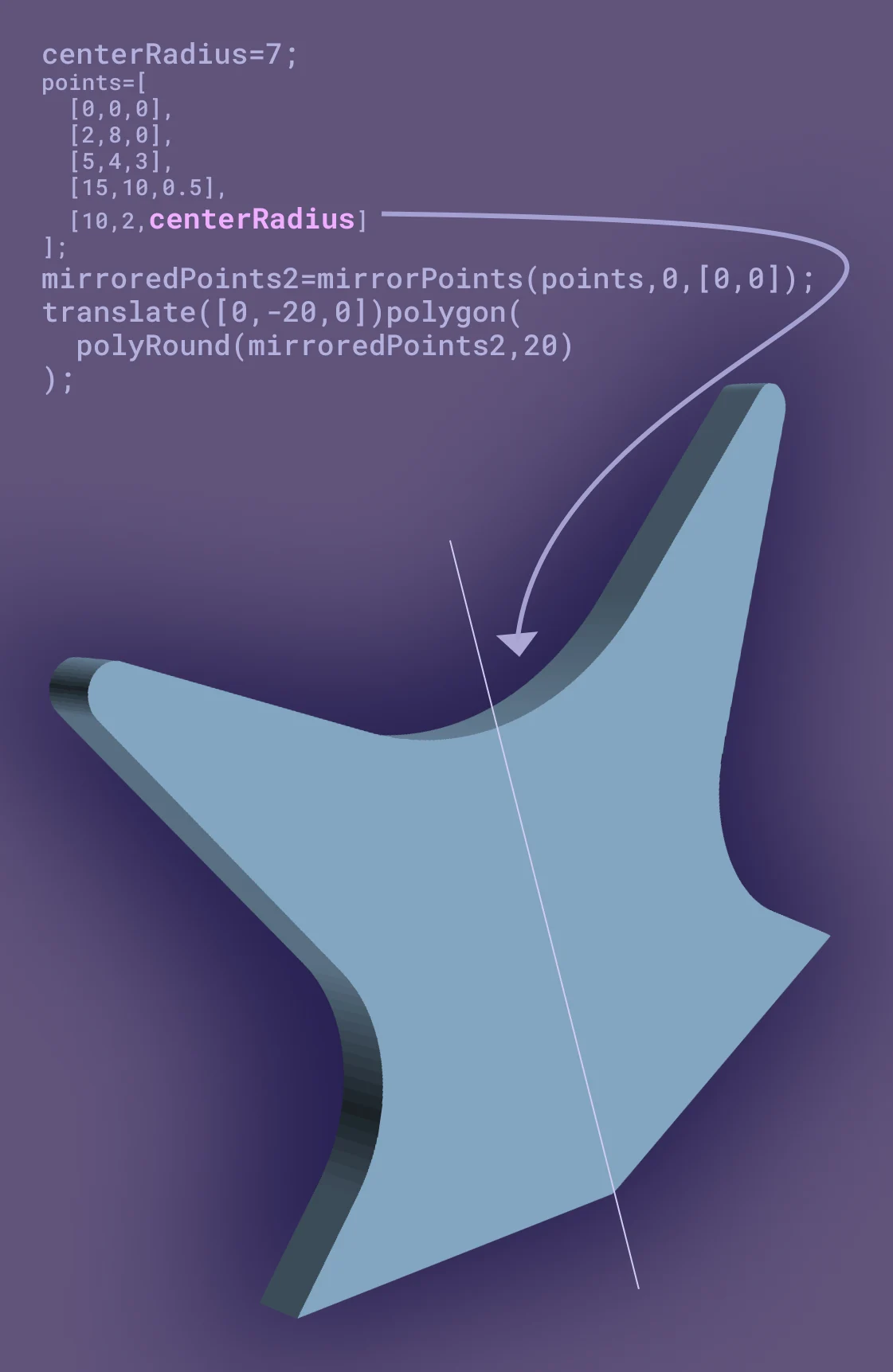
centerRadius=7;points=[[0,0,0],[2,8,0],[5,4,3],[15,10,0.5],[10,2,centerRadius]];mirroredPoints=mirrorPoints(points,0,[0,0]);translate([0,-20,0])polygon(polyRound(mirroredPoints,20));extrudeWithRadius#
Module for extruding a 2d child, with the ability to put a radius on each end of the extrusion. Fills the same role as polyRoundExtrude, though this module is more flexible as it's able to work on any 2d child, but is less preformant.
polyRoundExtrude is recommended over extrudeWithRadius if your use-case allows it.
use:
extrudeWithRadius(length,r1=0,r2=0,fn=30){ // 2D child}length: length of the extrusion.r1,r2: Start and end radii.fn: How much the radii are subdivided.
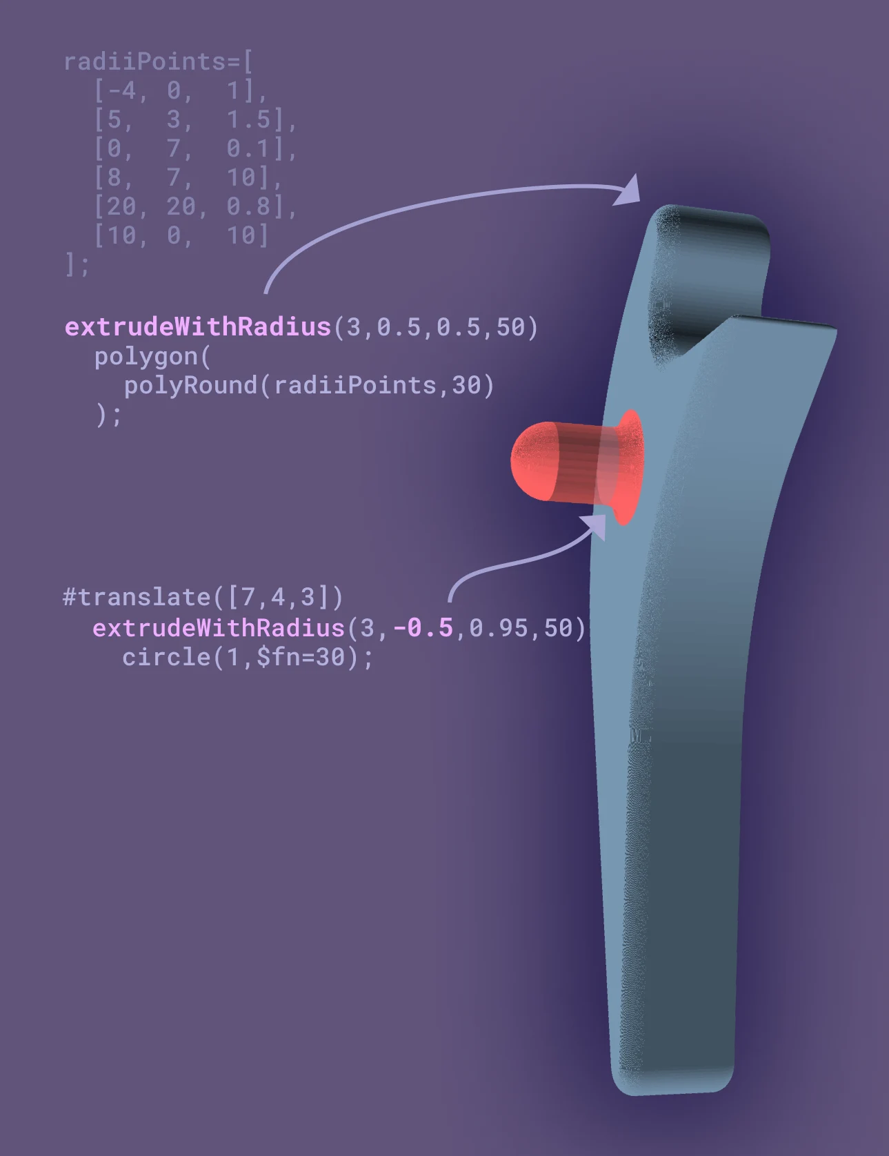
radiiPoints=[[-4,0,1],[5,3,1.5],[0,7,0.1],[8,7,10],[20,20,0.8],[10,0,10]];extrudeWithRadius(3,0.5,0.5,50) polygon(polyRound(radiiPoints,30));#translate([7,4,3])extrudeWithRadius(3,-0.5,0.95,50)circle(1,$fn=30);MinkowskiRound (not recommended)#
This module will round its children. External and internal radii are defined separately. The syntax is:
minkowskiRound(OR, IR, enable, boundingEnvelope) { // children}OR: Set the Outer radiusIR: Set the internal radiusenable: Toggle whether the rounding enabled, as the module is computationally expensive, so it's convenient to have an easy way to disable it.boundingEnvelope: An array with three values which should be large enough to capture the children
Because this module will round anything after-the-fact, it's useful adding radii to complex shapes that would be very difficult to do otherwise.
Such as the curving internal edge of this cube-cylinder union.
Despite this, our recommendation is to design part so that minkowskiRound isn't needed. Use of the minkowski module is too slow to be practical.
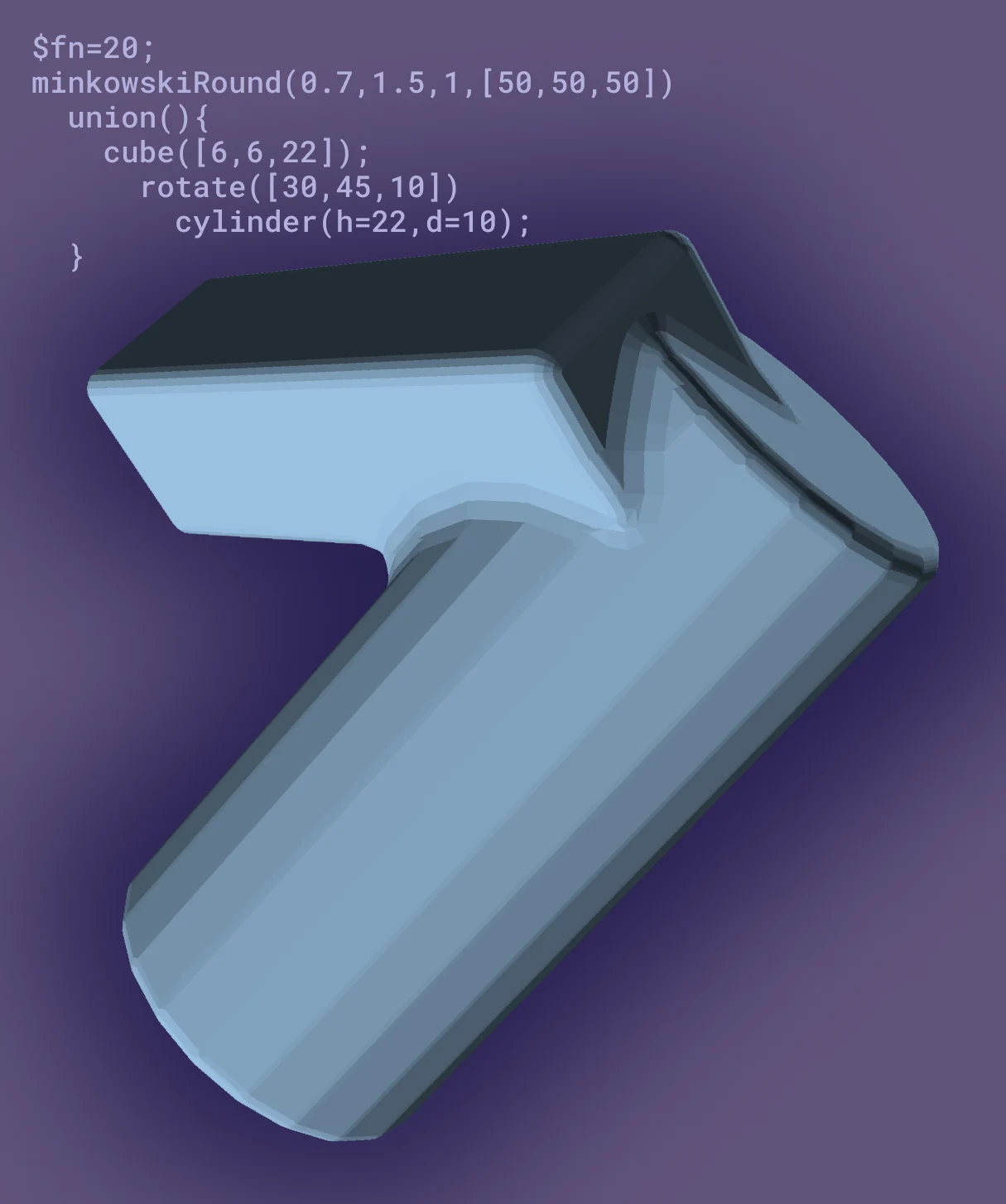
$fn=20;minkowskiRound(0.7,1.5,1,[50,50,50]) union(){ cube([6,6,22]); rotate([30,45,10]) cylinder(h=22,d=10); }